Objective
Component tests offer potential advantages to overcome disadvantages like the number of full-scale tests and the quality of the load distribution applied in the current certification procedure. Furthermore, they enhance detailed studying of structural damage modes and thorough model validations.
The potential integration of sub-component tests in the validation chain is schematically shown in the figure above for the example of a trailing edge.
Description of activities and methods
Within this work package, four large-scale tests will be developed and conduct.
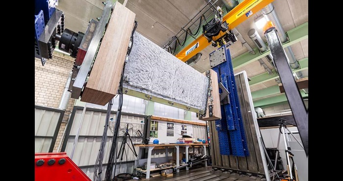
- Trailing Edge sub-component, see Figure 2: Trailing edge damages are one of the most often observed failures in wind turbine blades during operation. The corresponding modes are manifold and are depending on the actual detailed blade design. A well-designed test that realistically represents the relevant loading scenarios and boundary conditions is required. The work will be focused on the design of the load introduction area. For full cross-section blade segments, a downscaled general purpose test rig will be designed and build. The rig will be able to apply a bending moment around any axis of a cross-section of the blade. The test rig will also be designed for application of fatigue loads. Advanced control algorithms will be implemented so that complex fatigue loading can be obtained.

Figure 2. IWES Trailing Edge sub-component
- Debonding Transition Area generic element: The deformations in the blade transition area are high and result in a complex loading of the bond line. Therefore, this region is often seen as the most critical area for the spar cap to web bond line. Generic element tests that can realistically represent these loading conditions will be developed to validate fracture mechanics damage propagation models.
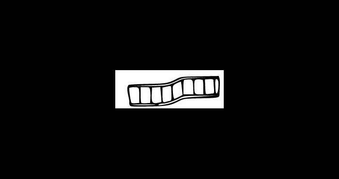
- Sandwich panel buckling resistance: In the blade structural evaluation the core shear buckling analysis is one of the most challenging predictions with highest uncertainties depending on the resin uptake. Therefore, a thorough model validation is required and thus, a component test set-up will be developed where panels with a representative size (slits and holes) and geometry will be investigated. A jig will be designed and constructed to be accommodated in a 2,5MN machine, towards testing composite plates with simple supported boundary conditions. Global modes as well as local ones will be investigated e.g. shear crimping, see Figure 2.

Figure 3. Shear crimping
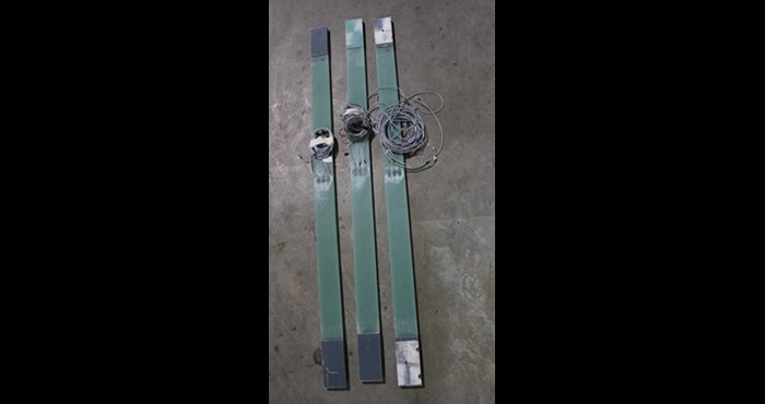
- Fatigue of thick composite laminates: Fatigue tests under tension-tension loading (e.g. R=0.1) is a standardized procedure. However, tests under (partial) compressive (e.g. R=-1 or R=10) loading require appropriate buckling supports. Testing of thick composites could be conducted without anti-buckling devices in a scaled geometry, see Figure 3.

Figure 4. Scaled Glass Fiber Reinforced Polymer specimens
Thick laminate reference samples that will be tested in a Mega-Newton universal coupon machine will be manufactured in a representative process for wind turbine blade spar caps. The process conditions will be closely monitored. Focus will be spotted in the load introduction area towards avoiding spurious damage modes.
Work Package Leaders / Contact
Alexandros Antoniou; Steen Hjelm Madsen