Objective
The objective of WP5 is twofold. First, to deliver physical and mechanical properties of the adhesive, composite materials and sandwich structures as input values for the blade design process. Second, to describe the mechanical performance of composite materials, through developing adequate material models, considering the curing development, the manufacturing intrinsic non-conformities and the wind induced multiaxial stress states.
Description of activities and methods
The scheduled activities are:
- Derivation of the material properties required for the full-scale blade design & manufacturing
- Modelling of the manufacturing effects on the material properties (curing degree, thermal/chemical stresses, relaxation, resin uptake, fabric undulations, waviness, Fiber Volume Fraction, etc.)
- Modelling of laminate and adhesive damage initiation and propagation
The material properties required for the manufacturing and the blade design procedure will be derived through thermo-mechanical testing according to national, international and in-house standards. An extended characterization matrix is foreseen, including uniaxial static and fatigue tests for the composites, four-point bending tests for the core materials, thermal mechanical analysis (TMA), Differential Scanning Calorimetry (DSC) and Dynamic Mechanical Analysis (DMA) for the determination of the physical properties.
Towards modelling the materials manufacturing dependent performance, focus will be spotted on:
- the polymers matrix (infusion, adhesive) and their properties evolution with the curing degree
- the glass-fiber fabric texture (fiber angle deviation i.e. undulations & waviness)
- micromechanical analysis based on the composite constituent materials

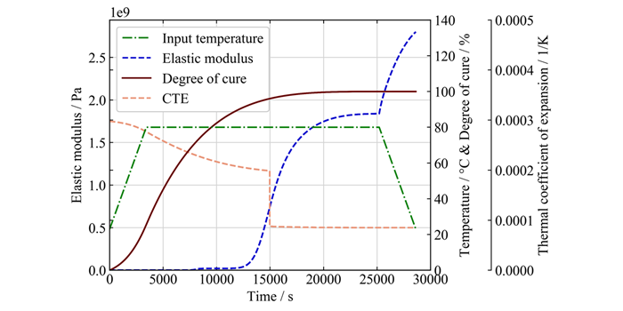
Figure 1. Development of Young's modulus and thermal expansion factor with curing degree and temperature profile
Thermal and chemical residual stresses are developing in the polymers during the curing process, depending on the applied temperature profile and the polymerization degree. The former are resulting from the differences of the constituent materials thermal expansion factors while the latest due to the density change with the curing degree. This is valid both for laminates and adhesive bond lines. In order to quantify the residual stresses, a modular step-wise analysis will be conducted. Thus, polymer curing degree evolution will be accounted through empirical curing kinetic models. The corresponding matrix stiffness development will be modelled as a function both of the curing and the operational temperature. The chemical shrinkage will be derived separately with an in-house experimental procedure and will be integrated accordingly in the analysis loop, see Figure 1. To account for relaxation effects and the resulting stiffness and stress reduction, the viscoelastic properties of the implemented epoxy resin systems will be determined and modelled.
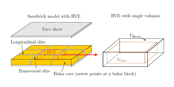
For the sandwich core, a resin uptake model will be developed based on the material (balsa wood) physical micro-structure of a representative volume element (RVE), see Figure 2. The model will predict the mass that is absorbed from the cellular core during the infusion process, calculating the effective stiffness performance of the sandwich structure.

Figure 2. Representative Volume Element (RVE) for core material
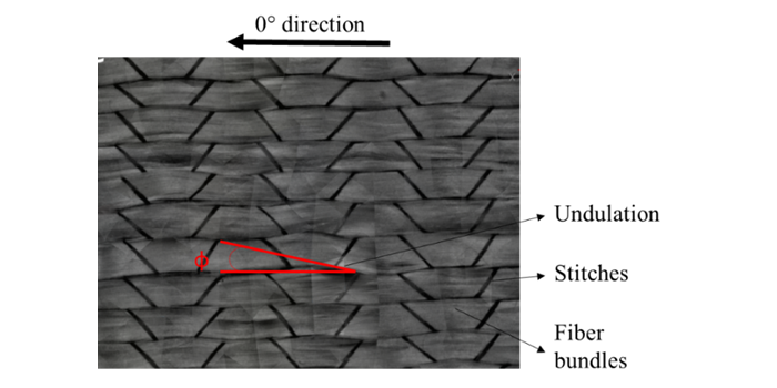
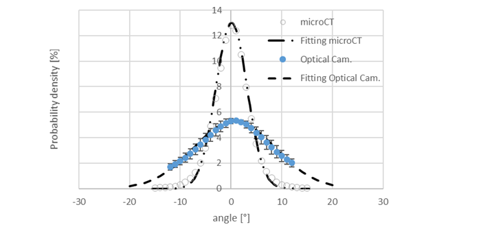
To account for the fabric-driven effects in laminate configurations, e.g. undulations, see Figure 3, non-conformities (waviness), the textile in-situ fiber angle distribution will be characterised experimentally with an integrated Camera system and with Computer Tomography. The statistical distribution of the fibers will be determined and modelled with respect to the 0° angle of the ideal unidirectional ply, see Figure 4. The distribution will be integrated in 2D and 3D lamination models generating multiaxial laminates. Each ply will get its properties based on micromechanical models which will be considering only the composite constituent materials i.e. resin and fibers. The corresponding prediction of the laminate stiffness and strength properties will be validated against meso and large-scale mechanical quasi-static tests.
 Figure 3. Non-crimp fabric
Figure 4. Fiber angle probability density distribution
Work Package Leaders / Contact
Alexandros Antoniou; Martin A. Eder